Hello! Who’s Online?
Enabling M2M Connectivity through GSM/GPRS
Internet of Things
Inter-networked sensors, intelligent devices, consumer electronics, commercial and industrial products along with wireless connectivity and cloud computing is making the “Internet of Things” (IoT) more realistic with each passing day. As said by Kevin Ashton (person who coined this term) “In the real world, things matter more than ideas”. The whole concept was to provide ability to talk to the end device or sensor directly, without human intervention, so as to get rid of human errors and inaccuracies and to greatly reduce loss, waste and cost.
Initially, the idea was to use RFID as last mile communication providing unique identification to each end device (or ‘thing’) and then interconnecting all the devices in an internet-like structure. However today, a large number of different communication media and technologies are being used to achieve this noble mission.
M2M – Machine to Machine
M2M, in brief, is an ability to connect with machines. IoT can be realized only when M2M is achieved. Ability to communicate with devices remotely not only enhances the accessibility, but can also improve performance of the overall system. Today, more than 50 billion devices are interconnected and they can provide seamless connectivity between machines. Further, widespread usage of IP networks has made it even easier. Devices can be designed as “IP-enabled” and can be communicated from anywhere.
The existing PSTN network can be effectively used to communicate with remote end devices. Below mentioned are the few applications that show a glimpse of M2M possibilities using the existing telephony network.
- AMI (Advance Metering Infrastructure)
A lot is happening in the energy sector since the last decade. Smart meters along with smart HAN devices are providing an ability to communicate with remote Meter Data Management (MDM) center, thereby, helping to convert grids to smart grids.
- Vehicle Tracking
In the logistic industry, vehicle mobility tracking, maintaining consignment delivery time, goods’ safety and the current condition of perishable goods are some of the key concerns. Using GSM based communication along with GPS enhancement is a worldwide successful solution for this. - Transportation Telematics
GPS guided real time traffic assistance, vehicle condition monitoring and automatic toll collection are few to mention in this category. Further driving behavior can also be monitored either real time or can be logged for post accidental analysis and insurance claim settlements. - Remote Patient Health Monitoring
M2M enabled at-home usable medical devices such as heart beat, blood pressure and glucose meters can help to send routine health conditions to doctor for a review of the patient’s health. Moreover, patients on life support systems can be monitored continuously and during an emergency, immediately contact can be established. - Home Security
Whether valued assets are safe when home is locked is always a concern. Security and alarming system assisted with online communication can help to keep home and business premises safe. - Emergency Services
Auto SMS and voice call connection during accidents is a widely used application in this segment. It can be further enhanced by using GPS to track down the accident location. In Europe, according to European Union eSafety initiative, soon, a regulation will be rolled out, mandating each new car with such an emergency call system. Apart from this, emergency call during panic situation such as sudden human attack can be made just by a press of a button.
Start Connecting!
This section provides a brief application note on how a readily available off-the-shelf GSM module (a.k.a. engine) can be interfaced, enabling your product for M2M connectivity.
GSM modules can be communicated typically via UART, SPI or USB using Hayes AT commands. These sets of commands help to configure parameters such as baud rate, flow control, numeric response code, unsolicited response behavior, APN, etc. and helps to perform set of operations like dialing, call pick up and hang up, sending and reading SMS, GPRS connection, etc.
Figure 1 shows the connection setup required to interface a GSM module. Following is the required part list.
- GSM/GPRS Module
- SIM Card and Holder
- Antenna
- Target Application Board
- Serial Cable
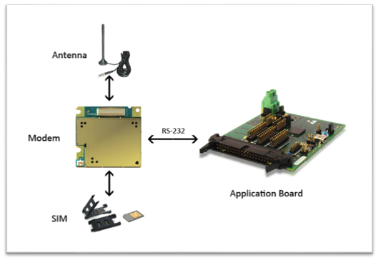
Figure 1 – GSM module interface connection
Figure 2 shows the basic flow chart for interfacing the GSM module. As shown in the figure, initially GSM module needs to be enabled, typically by applying a pulse on the ‘ignition’ pin. The module is then ready to accept AT commands and default parameters can be configured. If the network is available and a valid SIM card is inserted, it will be authenticated and registered to the network. At this stage, i.e. Status = Registered, application can run an idle task. During an idle run, GSM module may push unsolicited response intimating either different possible network conditions (such as SIM unregistered) or incoming call/SMS indication. Even SIM presence can be monitored if the ‘SIM presence’ pin from the SIM tray is connected to the module. Flow chart shows handling of data call, new SMS received and SIM related intimations, while all other unsolicited responses from the module are discarded.
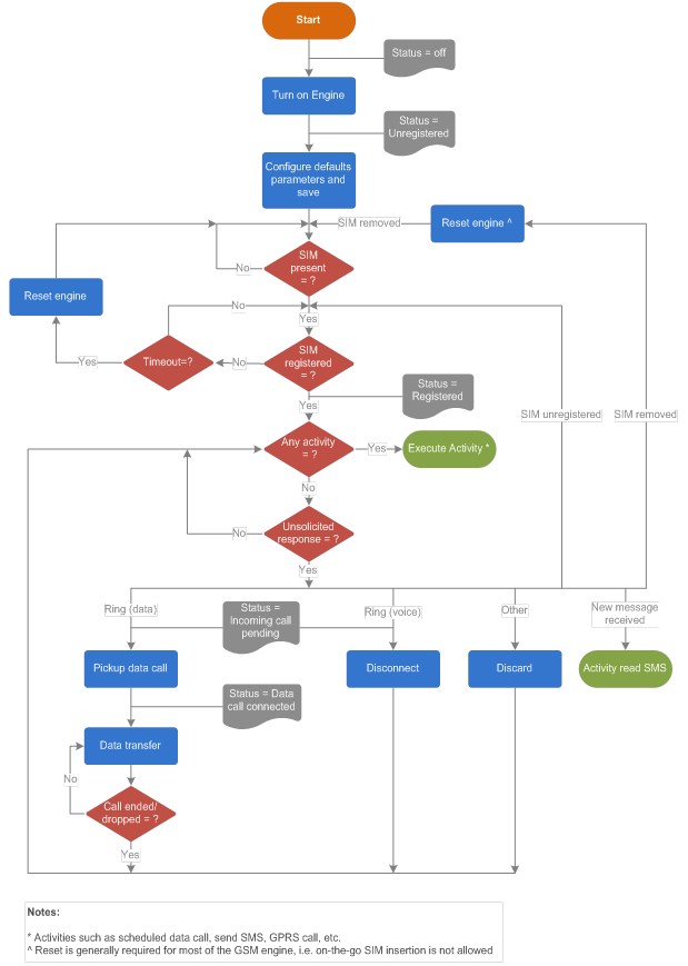
Figure 2 – GSM module configuration and idle run
Note that most of the modules need restart, if the SIM is removed and re-inserted, in order to get registered to the network; i.e. dynamic SIM insertion and extraction is not supported.
Besides handling incoming intimations from a module, an application may also trigger scheduled or event-based activities such as sending SMS, establishing a data call or connecting to remote server in order to transfer relevant data.
Figure 3 shows SMS related handling which involves AT commands such as AT+CMGR for reading and AT+CMGS for sending, along with some other commands required for SMS related configurations. GSM supports text and PDU (Protocol Description Unit) mode for sending and receiving SMS messages. The PDU is a special compression format used by most of the handset.
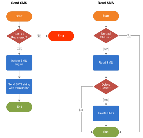
Figure 3 – SMS handling flow graph
Most M2M applications do not need voice call, except emergency services, when voice call support may be required in addition to SMS service. GSM network supports the so-called “data” call, which enables one to establish virtual serial connection with the remote machine.
Figure 4 shows data call initiation which involves ATD command followed by destination number.
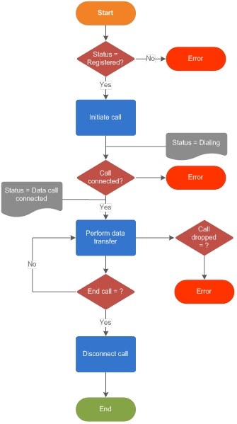 Figure 4 – Data call flow graph
Finally, GPRS service is the most appealing feature of GSM network, since it provides wireless internet connectivity. In order to enable IP connectivity, two approaches can be used
- Using inbuilt TCP/IP stack from the GSM module vendor
- Implementing TCP/IP stack on the target application board and using GSM module just to invoke GPRS call.
Approach 1 is easier and removes issues such as learning curve, stack license purchase (in case commercial third party stack is to be used) and possible implementation level bugs. However, this approach forces to use vendor specific AT commands and hence creates vendor locking situation. Also, the user has to live with all possible bugs inherent in the implemented stack within the module.
Approach 2 provides a better hold on the situation such as vendor independence and ability to fix any encountered bug in the stack. With this approach, however as mentioned, a thorough knowledge of TCP/IP stack will be required. As a solution, it is better and faster way to adopt third party pre-written stack, either open-source such as lwIP, uip, uc/IP, FNET, etc. or commercial one like CMX-Micronet, Nichelite, etc.
Figure 5 provides GPRS connection flow diagram using approach 2 considering CMX-Micronet as third party stack.
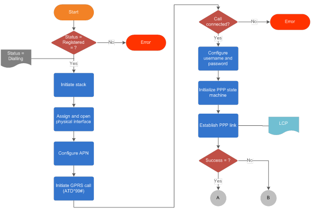 Figure 5(a) – GPRS communication flow graph, Part – 1
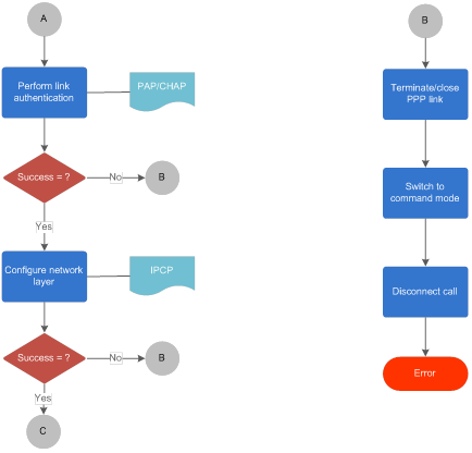
Figure 5(b) – GPRS communication flow graph, Part – 2
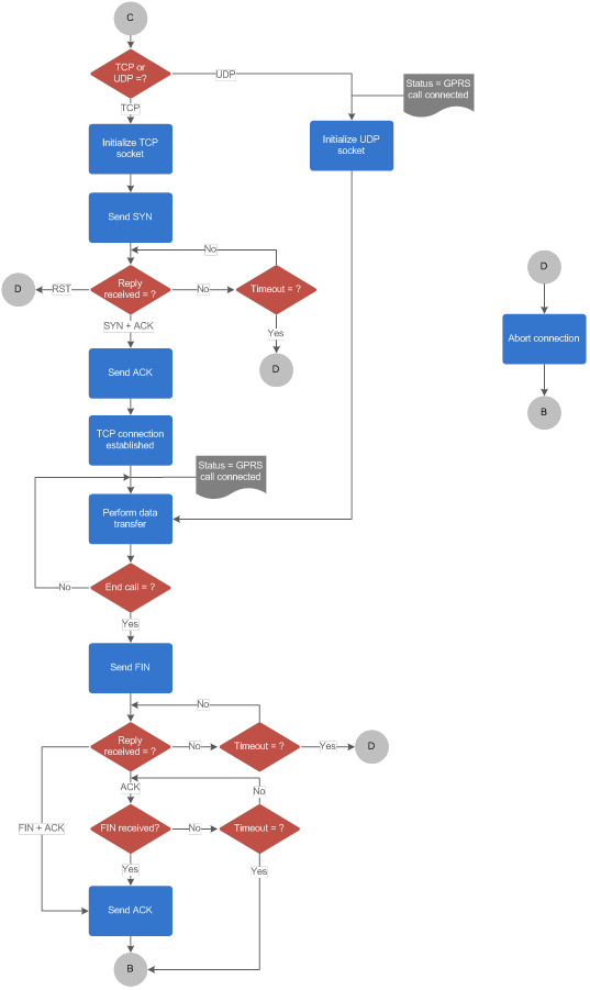 Figure 5(c) – GPRS communication flow graph, Part – 3
Connecting to IP network using GPRS involves the following steps
- Configure APN and initiate GPRS call using AT command
- Setup PPP connection
- For active mode (i.e. client), if TCP is used, setup TCP connection
- For passive mode (i.e. server), setup server
- Relay data over TCP or UDP
Whereas, disconnecting involves the following steps
- If TCP used, close the connection
- Close PPP connection
- Switch back to command mode and hang up the call
Once the basic IP stack is working, as a further step, one may add security protocols such as SSH, SSL, IPSec, etc. or can run applications such as web server or email in order to enhance functionality of the product.
Final Words
Today, amidst the large number of communication technologies and media, GSM based M2M connectivity can be effectively used to achieve IoT. With GSM services getting better and cheaper over the period, this approach will further help to provide IP connectivity to the end devices.
References
- That “Internet of Things” Thing, Kevin Ashton, RFID Journal, July 2009
- “AT command set for User Equipment (UE)”, V10.7.0, 3GPP TS 27.007, Mar 2012
- http://m2m.gemalto.com/
- CMX Micronet Stack, http://www.cmx.com/micronet.htm
- NicheLite TCP/IP Stack, http://www.iniche.com/nichelite.php
- lwIP, http://savannah.nongnu.org/projects/lwip/
- uip, http://sourceforge.net/projects/uip-stack/


