
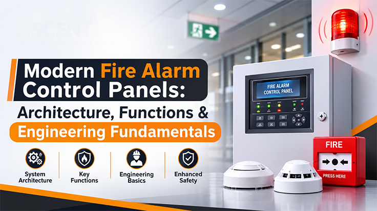
The fire alarm control panel is a device that takes decisions and does the processing of information regarding the fire detection system. Information about the fire detection system is provided to the fire alarm control panel through different devices that initiate the alarm.
The fire alarm control panel is not only a controller but also has other aspects that engineers can relate to the system.
FACP continuously supervises all connected initiating devices and field circuits. Upon sensing any fire condition through any initiating device such as a smoke detector, heat detector, manual call point, or others, the controller assesses the input condition and sets the system in alarm mode.
The same arrangement deals with any trouble condition, including open circuit, short circuit, loss of communications, loss of power, or low battery conditions. Supervisory input signals include valve positions and statuses of other equipment under supervision.

This architecture separates power, processing, field interfaces and communications while allowing the firmware to coordinate the complete system.
A typical modern FACP can be viewed as a series of connected functional blocks. The field devices provide inputs to the panel, the controller processes those inputs, and the resulting events are passed to notification, building and monitoring interfaces.
Power, supervision and security are cross-cutting functions across the architecture. Their implementation affects the field interfaces, controller, communication paths and output stages rather than being limited to a single functional block.
The traditional system separates the detectors into zones and determines the zone rather than the device itself. An addressable system assigns an address to each of the field devices so that the panel is able to determine the particular detector or module.
An intelligent system enhances this by adding information about the devices, diagnostic ability, programable logic and enhanced event management. Depending on the design of the system, the devices can provide more information that will enable the controller to differentiate between alarms and environmental changes.
The detection circuit is used to link field devices to the controller. In an addressable system, the signalling line circuit (SLC) acts as the communications and power link for the devices supported.
The hardware should be able to manage wiring under conditions that may arise from any abnormal situation but still maintain communications with the field devices.
After the alarm determination, the alarm controller initiates notification appliances like horns, sounders, strobes, and evacuation interfaces. The NACs should have supervised output stages that can detect any wiring problems and still meet the necessary load.
Additional output interfaces may control relays, auxiliary equipment or building interfaces. Isolation and protection are important because external loads can introduce electrical transients into the controller.
Fire alarm electronic circuitry requires the use of a supervised power structure. The power module usually consists of an AC input, DC regulation, battery charging, and monitoring.
Battery backup ensures that the circuit continues to function even in the absence of power. Both hardware and software can monitor conditions like low battery, charger failure, AC input loss, and supply voltage problems.
The main MCU will execute the embedded firmware that performs tasks such as device polling, event categorisation, system state management, user interface, diagnosis, and communication.
The input modules enable the controller to get signals from the outside devices, whereas the output modules provide an interface to appliances, relays, and other equipment.
Events are generally processed into defined states such as:
Alarm
A confirmed fire-related initiating condition requiring immediate warning and evacuation.
Trouble
A system or circuit fault requiring attention (such as open/short circuit, ground fault, or loss of communications).
Supervisory
A monitored condition requiring notification without representing a fire alarm (such as valve positions or equipment status).
Normal
Monitored circuits and all system functions are operating within expected design parameters.
The firmware must prioritise events correctly and maintain predictable behaviour under simultaneous inputs.
FACP development requires decisions across hardware, firmware and system architecture. Increasing capability in one area can affect power consumption, PCB complexity, processing requirements, cost, serviceability or system reliability.
| Engineering area | Primary consideration | Typical trade-off |
|---|---|---|
| Power supply | Stable regulated power for electronics and field circuits | Higher capacity improves available load but increases size, thermal requirements and cost |
| Battery | Backup capacity and charging performance | Larger battery capacity improves backup duration but increases enclosure size, weight and charging requirements |
| MCU | Processing capability, memory and peripheral support | A more capable MCU supports complex event processing and communications but can increase power, cost and software complexity |
| SLC | Device communication, addressing and circuit supervision | More devices and longer communication paths increase system capability but place greater demands on signalling, supervision and fault handling |
| NAC | Output current, supervision and load handling | Higher output capability supports more notification loads but increases power and thermal requirements |
| PCB | Routing, isolation, protection and component placement | Greater circuit density saves board space but makes isolation, thermal management, EMC and servicing more demanding |
| Redundancy | Availability and fault tolerance | Additional redundant paths or components can improve resilience but increase hardware, testing and maintenance requirements |
| Communication | Remote monitoring, BMS and connected systems | Greater connectivity improves monitoring and diagnostics but adds interface, security and firmware requirements |
| Firmware | Event processing, diagnostics and system control | More functionality improves system capability but increases software complexity, validation and maintenance effort |
These trade-offs need to be considered together because a change in one subsystem can affect the rest of the FACP. For example, increasing field-device capacity can influence SLC design, power requirements, MCU resources, PCB layout and firmware complexity.
Reliability is central to FACP engineering. Designs can incorporate supervised communication paths, protected power rails, watchdog mechanisms, memory integrity checks, circuit isolation and fault reporting.
Where system architecture requires higher availability, redundancy can be introduced at selected controller, communication or power levels. The objective is to prevent a single component failure from silently disabling critical monitoring or notification functions.
The modern panels have capabilities to interface with the remote monitoring system, building management system, and other fire and safety devices. The interfaces may be through wired communication networks, gateways, or IP-based communication based on the architecture of the system.
The connected FACP is capable of remote diagnostics, event logging, remote programming, and system status monitoring. This places an emphasis in engineering on secure communications, firmware, and cybersecurity.
Contemporary FACP systems will integrate an integrated system solution that integrates sensor data, processing of the information in real-time, communications and intelligent diagnostics. With more powerful MCUs, connectivity and better firmware, manufacturers can develop systems with more intelligence built into them.
This calls for proper integration of hardware development, embedded software, circuit board design, power management and communication capabilities when developing an FACP system.
Build reliable fire and safety electronics with Ascenten
Ascenten offers expertise in electronics R&D, hardware engineering, embedded systems, IoT, and product engineering for fire and safety products. If you are designing a new fire alarm panel, connected safety control panel, or any other embedded product, contact Ascenten to talk about engineering requirements.
Connect with AscentenContact Us
We would really like to hear from you and answer any questions. Please email us at info1@ascenten.net
or call us on
India Landline: +91-79-2646 4646
India Mobile: +91-89800 00973