
A smart meter is an embedded system in a small package that converts utility measurements into authentic data. Its accuracy depends on the complete signal chain, from sensing and analog conditioning to metrology, firmware, communications and security. Ascenten’s experience in metering, analog and digital design, embedded software, algorithms and connected systems reflects the cross-domain engineering required to build such products.
A typical smart meter architecture can be represented as:
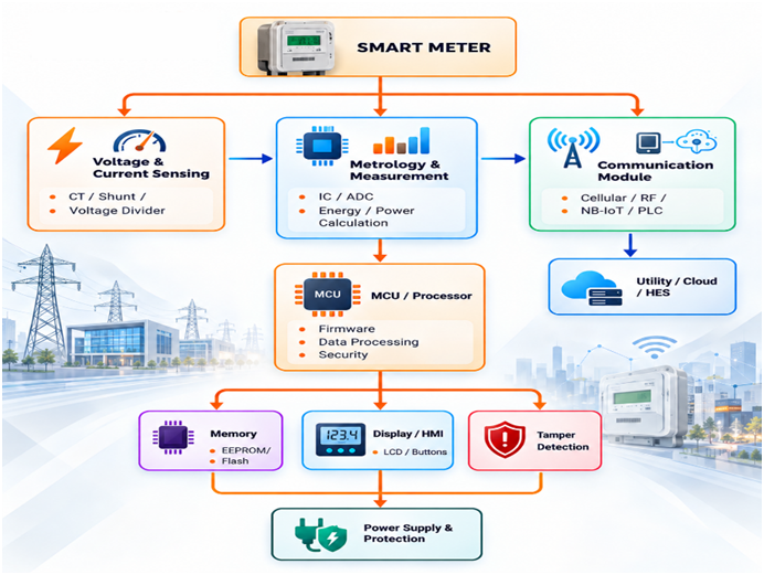
Implementation may differ from one energy consumption metering application to another, such as electricity, gas or water, but the underlying philosophy is common – obtain the physical measurement, digitize it accurately, process, store and communicate it.
The entry point for measurement in an electricity meter is the voltage and current measurement system. Current can either be sensed using current transformers or shunts, depending on the meter design, while the voltage measurement usually involves scaling by a proper sensing circuit. The gas and water meters have flow-based sensing mechanisms.
The analog front end conditions these signals before conversion. Filtering, gain, protection, isolation and anti-aliasing have to be considered together because noise or distortion introduced here can directly affect measurement accuracy. PCB layout, grounding and signal integrity also become part of the metrology problem.
The ADC converts conditioned analog signals into digital samples. A dedicated metrology IC may then calculate parameters such as RMS voltage, RMS current, active energy, reactive energy, power factor and frequency. Some architectures place more of these functions inside the MCU through firmware algorithms.
Calibration is equally important. Meter constants and calibration coefficients may be stored in non-volatile memory so that the measurement chain can be corrected during production and maintained across the product lifecycle. Ascenten has documented metering algorithm work focused on balancing computational load, power consumption and measurement resolution.
The MCU coordinates the meter. It manages sensor interfaces, metrology data, communication stacks, diagnostics, tamper events, display functions and firmware updates.
Non-volatile memory is used to store configuration, calibration information, event logs, and accumulated measurements. RAM enables real-time calculations, while RTC gives time-related references for intervals, billing cycles, logs, and scheduling functions.
The local display gives users access to readings, status information and diagnostic indicators. Buttons, optical interfaces or service ports can provide local configuration or maintenance access.
Stable operation should be maintained by the power subsystem, which operates amid fluctuations in the power supply and electrical interference. Secondary storage or power source may provide power to certain modules during failure using the design of the meter.
The communication module is used for connecting the meter to the AMI system. Connectivity options include RF Mesh, PLC, cellular (e.g., NB-IoT or LTE Cat-M), Ethernet, and other types of interfaces. Ascenten’s smart-meter work includes communication protocol integration and DLMS/COSEM-related development.
A practical firmware stack is often organized such that hardware abstraction and drivers are separated from metrology, application functions, memory and other services. Such an approach allows simplifying testability and future maintenance. Bootloaders and managed firmware updates are also required for meter deployments in the field.
Security cuts across the architecture. Device identity, authentication, protected storage, secure communication, access control and firmware integrity should be considered from the beginning. A smart meter is a networked endpoint, so measurement integrity and communication security have to be treated as connected engineering requirements. Ascenten’s smart-meter work also addresses secure communication, firmware updates and meter configuration.
At the system level, the meter sends out readings, events, alerts and settings. This type of structured communication between meters is often based on DLMS/COSEM, but different types of networks can be used for the lower-level transport. The HES can then send out the data to the billing and analysis systems.
Engineering a reliable meter therefore requires coordination across the entire chain. Ascenten brings together hardware, PCB, embedded firmware, algorithms and communication expertise, supporting smart-meter development from architecture and prototyping through testing and production engineering.
Smart meter design requires much more than picking up the right parts. Engineers have to consider the trade-offs between performance, reliability, cost, power efficiency, security and maintainability in the whole system.
- Sensing: More accurate sensing parts can enhance sensing accuracy and stability, but at a cost of increased BOM cost, PCB space and calibrating effort. The sensing technique should thus be chosen considering the accuracy and range of operation, and also the cost of the target product.
- AFE and Metrology: Higher resolution, better filtering and increased complexity of metrology algorithms may enhance performance; however, they might require greater computational capabilities and higher costs. It is necessary to find a compromise between accuracy, resolution and expenses, computational power and efficiency.
- MCU: A more capable MCU can handle advanced metrology, communication stacks, diagnostics and security functions with greater flexibility. However, higher processing capability can increase cost and power consumption. The MCU should therefore provide sufficient headroom without being unnecessarily oversized for the application.
- Memory: More flash and RAM provide greater flexibility for firmware, event logs, security functions and future features. At the same time, memory selection affects BOM cost and power requirements. The memory architecture should account for both current requirements and the expected field life of the meter.
- Communication Technology: Communication technology is characterized by trade-offs with regard to coverage, bandwidth, network availability, latency, and power consumption. RF Mesh, PLC, and cellular communications can have varying deployment considerations; therefore, the choice of communication architecture should depend on where the meters will be deployed.
- Security: Enhanced authentication, encryption, secure boot, secure storage and protection against malicious code attacks provides better security from any attacks. But security features utilize system resources such as processing capability, memory and even hardware. Thus, security cannot be a secondary concern; it must be built into the system resource budget right from the start.
- PCB: Compact PCB designs can reduce size and material cost, but dense layouts can make signal integrity, isolation, thermal management and EMC performance more challenging. Sensitive metrology signals and communication or power sections often require careful placement, routing and grounding to maintain measurement reliability.
- Power: Meter electronics must operate reliably under supply fluctuations and electrical disturbances while meeting efficiency requirements. Higher processing, communication and security activity can increase power demand, making power architecture and operating modes important considerations for the overall design.
- OTA and firmware updates: Over-the-air updates allow deployed meters to receive security patches, bug fixes and feature improvements without physical access. However, OTA introduces additional requirements for secure boot, firmware authentication, rollback handling, memory management and communication reliability. The update mechanism must therefore be designed alongside the firmware and security architecture.
These trade-offs are interconnected. A decision to improve one part of the system can affect several others. For example, a higher-resolution metrology implementation may require greater processing capability, additional memory and more power, while stronger security can increase firmware and computational requirements. For R&D and engineering teams, hardware, PCB, firmware, metrology, communication and security must therefore be architected together rather than treated as independent design activities.
For companies developing or upgrading connected metering products, Ascenten’s smart meter design services can help translate measurement, connectivity and embedded requirements into a practical product architecture.