USB 2.0 to Ethernet Converter

The market today is inundated with various converters and one can find a multitude of USB to Ethernet converters – those that work in the temperature range of -25 to +50 degree Celsius and can convert USB 2.0 to Ethernet and vice versa. In other words, these are more like one-way conversion units and generally suitable to use with laptops or general computers only.
However, a converter that can work on an industrial USB 2.0 port and function in the temperature range of -40 to +85 degree celsius is not easily available in the market. An industrial USB port is by design different from the normal USB ports of computers.
Ascenten has developed a single card with a universal approach, that can convert either a USB 2.0 to 10/100 Mbps Ethernet or a 10/100 Mbps Ethernet to USB 2.0. This bi-directional Ethernet and USB connectivity card carries an industrial-grade USB 2.0 port and is therefore capable to withstand a wide operating temperature range (-40 to +85 degree celsius).
This card supports many important features, as mentioned below-
- Auto-polarity and auto-negotiation detection
- 10/100 Mbps half & full duplex modes
- Auto-MDIX mode
- Single-chip, high-speed USB 2.0 to 10/100 Ethernet converter
- ±5kV HBM and ±15kV air discharge ESD protection
- One 25MHz crystal
- EEPROM-less design (helps reduce BOM)
- 8x8mm, 57-pin QFN package (well-suited for compact designs)
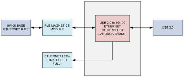
The 3.3V supply required to power the board comes from either the USB or the Ethernet port. The block diagram illustrates architecture of the USB to 10/100 RJ45 Ethernet converter.
 |
|
USB 2.0 to 10/100 Ethernet Converter Block Diagram |
Although the design looks simple, there are several key aspects that need careful attention while planning the design and layout on the PCB.
a) For achieving best performance, the center tap connections on the transmit channel and receive channel must be connected to receive and transmit channel of the magnetic module accordingly. Using auto-MDIX style magnetic module becomes necessary while using the LAN9500Ai chip in the auto-MDIX mode of operation. The best suited for this, as per SMSC guidelines, is ‘TG110-E055N5’.
b) The twisted pair (transmit and receive pins) of LAN9500Ai is connected to 49.9 ohm pull-up resistor. These pins are also connected to transmit and receive channels of the magnetic module. To determine the size of the resistors in the Ethernet front end, worst case operating conditions are considered. These comprise power safety factor (according to industry standard, range is 1.5 to 5.0 – application specific), total power through the 49.9 ohm resistor and power derating over temperature (industrial & commercial). Based on these, we chose a 49.9 ohm resistor of SMD_0805 size with a safety factor 2.
c) Utilizing the chassis ground is also an important factor in designing an Ethernet enabled product. The main intent here is to restrict any abnormal high-energy pulse from the digital ground plane and the digital power planes of the PCB. These high-energy pulses can cause erratic system behavior and / or cause semiconductor damage. Moreover, other voltage planes, signal trace or components need to be at least 0.250″ away from the chassis ground. The PCB chassis ground along with the Ethernet magnetics provides complete isolation for the system from the outside world. The unused pins of RJ45 connector are typically resistively connected to a high voltage capacitor to the chassis ground of the PCB. This prevents any high energy from entering the system and disturbing other electrical components and devices connected to the card.
d) The criteria for crystal oscillator selection is the frequency stability. The three main parameters which can change the crystal frequency are temperature, frequency deviation over time and frequency tolerance. As per IEEE 802.3u standard, total PPM bit budget allowed is ±50 PPM. Another important criterion is the drive level of the crystal, which must be in the range of 300uW to 500uW. A higher drive level can cause damage to the crystal which may then run at an incorrect frequency, parasitic resonance and phase noise thereby degrading the performance. For best performance, a 25.000 MHz crystal has been chosen, which suits the above requirement.
e) A 4-layer PCB design is preferred because running signals unreferenced to non-contiguous power planes may lead to signal integrity issues. Also, impedance matching helps manage comparatively cleaner signals, which is an important requirement in Ethernet and USB connections.
This card, although specifically built for a customer, can be used with any system that operates in the industrial temperature range. Functional enhancement and design and cost optimization were the key benefits of this engineering effort.


usb modem 2.0 convert ethernet output