Today’s demanding applications require components and systems to work under intense environmental conditions. Survivability is critical, as features are only as good as their ability to operate without fail.
Innovation in thermal management has become essential to meeting the requirements for fault-free performance. The choice of an appropriate thermal management system depends on cost and development time of a product. The techniques for heat dissipation include heat sinks and fans for air cooling, liquid cooling and peltier cooling (Thermoelectric cooling) etc. Designing a cost competitive electronics system requires careful consideration of the thermal domain also. To find the most optimized solution requires a good understanding of thermal properties of devices and knowledge on how to remove unnecessary heat from the devices.
This article presents the basic properties and principles of the thermal system of a device and the method of selection of a heat sink to prevent overheating under normal operating conditions.
 |
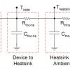
| Figure 1: Thermal circuit |
The following procedure provides a method one can use to determine whether a heat sink is required. This example uses a semiconductor device, with the condition listed below.
(1) Power – 20W, (2) Maximum TA – 50 °C, (3) Maximum TJ – 85 °C, (4) Air flow rate – 400 feet per minute, (5) ƟJA – 4.7 °C/W, (6) ƟJC – 0.13 °C/W.
| 1. | Using the junction temperature equation, calculate the junction temperature under the listed operational conditions: | |||||||||
| TJ = TA + P × ƟJA= 50 + 20 × 4.7 = 144 °CThe junction temperature of 144 °C is higher than the specified maximum junction temperature of 85 °C. So a heat sink is absolutely required to guarantee proper operation. | ||||||||||
| 2. | Using the heat-sink-to-ambient equation (and a ƟCS of 0.1 °C/W for typical thermal interface material), calculate the required heat-sink-to-ambient thermal resistance: | |||||||||
|
||||||||||
| 3. | Select a heat sink that meets the thermal resistance requirement of 1.52 °C/W. The heat sink must also physically fit onto the device. The thermal resistance of Z40-12.7B at an air flow of 400 feet per minute is 1.35 °C/W. Therefore, this heat sink will work since the published thermal resistance ƟSA is less than the required 1.52 °C/W. Using this heat sink, and re-verifying: | |||||||||
|
||||||||||
| 81.6 °C is under the specified maximum junction temperature of 85 °C. This justifies that the Z40-12.7B heat sink solution will work. |


No Comments